What Makes The Array Work
The K7TJR
Array
![]()
![]()
![]()
![]()
![]()
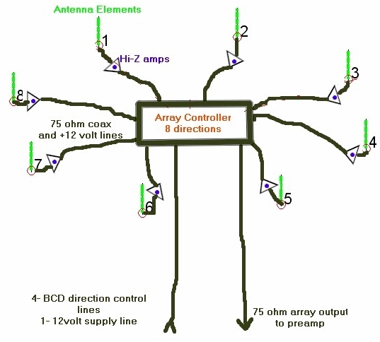
This array
consists of 8 vertical antenna elements and their support posts. Each antenna
element is essentially identical to all the others. The base of each element
feeds its own high impedance low gain buffer amplifier. Each amplifier is
gain and phase matched and includes a reference Earth ground rod connection at
its input. These amplifiers each feed their own 75-ohm coaxial cable to the
array controller. Each of the eight coaxial cables carries a separate 12-volt
supply line from the controller providing power for each amplifier. The
controller selects and combines the signals of all 8 antenna/amplifier
combinations. Some signals are processed without added delay and some require
the use of extra phase delay provided by coaxial delay cables. The Binary Coded
Decimal (BCD) control wire allows for remote switch selection of 8 available
directions while only using 4 wires. One extra wire on the direction control
cable supplies power from the shack to the entire array. The antenna signals
are processed in the controller according to the phase distribution shown in
the previous Geometry and Performance description, Combined signals are then
sent out the array output cable to the receiver or preamp/receiver combination.
The
Antenna Elements
The antenna
elements for this array were chosen to be 20 feet tall and constructed from
inexpensive “off the shelf” steel EMT tubing. In evaluating different lengths
for the elements one must take into consideration available signal output level
at the operating frequency in addition to output impedance. Very short elements
show an output impedance of a few ohms in series with a small capacitance. A 20
foot 1 inch diameter vertical exhibits 60 Pico-farads while a 10-foot vertical
is down to 35 Pico-farads series capacitance. A ten-foot long small diameter
whip is down to 24 Pico-farads. This
array is very sensitive to amplitude or phase differences between antenna
signals. Any significant percentage of this elements capacitance as a load to
the element will cause a shift in element output level. The antenna mounting
arrangement as well as the amplifier input must be designed to minimize any
stray capacitance. Any attempts I have tried to resonate out the capacitance loading
effects have ended in phase or amplitude control failure. Measurements were
made that confirmed as much as 10db signal increase by optimizing the element
mounting arrangement.
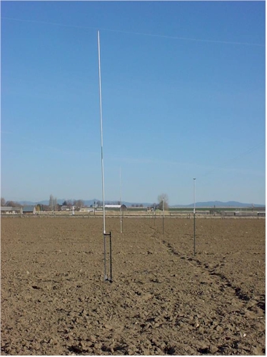
The actual element is made from one each ten foot section of ½ inch steel EMT electrical tubing slid 4 inches into a 10 foot section of ¾ inch EMT. The two sections were then welded together forming a single 19 foot 8 inch element. Cold Galvanizing paint was used to seal the newly welded areas for rust prevention. As shown in the picture the elements are spaced away from their mounting post to lower the stray capacitance to ground. To the right of the element in the foreground of the previous picture is a 1000-foot Beverage antenna used for comparison and evaluation of the array. My original element mounting simply strapped the elements to the post with their PVC pipe insulators. It worked, but changing this mounting arrangement made in excess of 6 db of received signal strength increase from a single element.
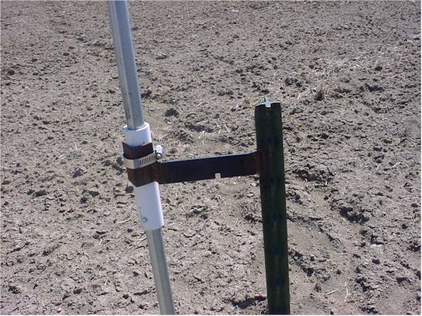
The antenna element is insulated
using a pair of seven-inch sections of PVC pipe. The top insulator is
automotive hose clamped to the mounting post using a 6-inch by 1-inch metal
strap welded to the post. At the end of the strap is a 2-inch long piece of
angle iron welded to form a saddle for the insulator and hose clamp. The 6-inch
strap is also welded to the post forming a solid mount. The bottom mount is
constructed from a 6-inch section of round rod stock with a 2-inch long ½ inch
diameter bolt welded to the outer end. The rod is welded to the post and the
bolt end is simply inserted through a ½ inch hole across the bottom of the PVC
insulator. The posts are standard lightweight “Tee” posts used for farm
fencing. They are 5-1/2 foot long with a bit over 4 foot extending above the
ground. I have also welded on a small plate for use as a ground connection just
above the ground level. These antenna mount posts were designed for easy
dismantling as this antenna is removed from its field each spring to allow
farming operations.
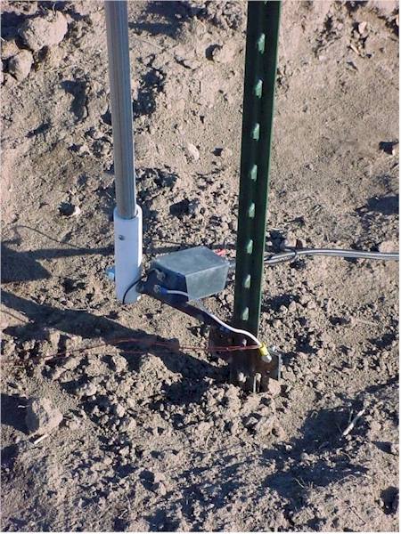
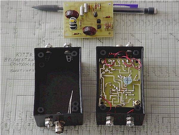
You can see in the picture remnants of some short radials that were tested and found to be unnecessary with my local soil characteristics. The ground impedance provided by the post itself is low enough that there is minimal impact on the signal as applied to the HI-Z amp. This mounting arrangement has been quite satisfactory and has only resulted in wind tipped elements once. The farmer plowed the field just before the Fall-season array installation leaving the ground quite soft. The elements were simply straightened up and the posts packed down again. You can see the Hi-Z amp in the little black box with its input and output connections. There are 8 of these identical and evenly spaced element/amplifier combinations in the 200-foot diameter circle.
The High
Impedance Amplifiers
The requirements for the Hi-Z amplifiers for this array were for the amplifiers to be very phase and amplitude stable. This meant that they must have a very low input capacitance and high input resistance. The amplifier also had to handle a significant amount of signal from local A.M. broadcasting stations and high power 160-meter contest signals. And lastly they had to have an adjustable gain and 75-ohms of stable output impedance.
In order to
assure that each element would be supplying accurate signals to the combiner
all 8 of these amplifiers were subjected to a battery of tests. The bandwidth
of the amplifiers were purposely set and measured at 85 Megahertz in order to
minimize phase shift at the 1.85 Megahertz operating frequency. Bandwidth is
mostly controlled by R5 and could be changed some if desired. Most tests were
conducted at 1-volt RMS output or less into a 75-ohm load. Total phase delay was
measured at 1.84 Mhz and found to be a consistent three degrees (mostly due to
the output transformer). Raising the input test voltage to the amplifiers will show 1-db
gain compression at a level of thirteen volts peak to peak at the input (less
with lower supply voltages). This corresponds to an output level over 15dbm
into the 75-ohm load. When using previous amplifier designs that could not
handle this level of input/output some BCI was evident in the system. Lastly
the amplifiers have been thoroughly isolated from undesirable common mode
currents by the output transformer and power line/ground inductors. There is an
input protection circuit included in the design however I have not needed to
use it in any arrays I have built so far. My original thought was to replace
R1, the 27-ohm resistor with a filament light bulb to absorb any incoming local
transmit signal energy when the amp input was shorted. I have not needed or
tested this yet. The amplifiers fit nicely into a commonly available plastic
enclosure.
Tests were set up with two side-by-side (20 foot separation) antenna elements with amplifiers plus their connecting cables to determine if phase and amplitude errors would be an end of the road for the array design. Known signals were injected into the antenna elements and then measured at the end of the cables that would attach to the controller. All amplifiers with cables and antenna elements were tested with the resultant phase shift differences less than 1 degree and amplitude differences less than 2 percent at 1850 Khz. Plugging these values of error into Eznec shows a rather insignificant change to RDF or front to back ratio of the array. Hi-Z amp Circuit boards, parts or completed and tested Hi-Z amplifiers are available by going to www.hizantennas.com . The controller accepts signals from all 8 Hi-Z amplifiers at the center of the array.
copyright K7TJR
Page 3
![]()
![]()
![]()
![]()