Eight Element All Active
Array
Geometry
and Performance
The K7TJR
Array![]()
![]()
![]()
![]()
![]()
This all-active
8-element array evolved from my fascination with the Eznec programs written by
Roy W7EL. While evaluating literally dozens of different antennas for low-band
low-noise reception it became apparent that the 4-element, wide-spaced, and
broadside arrays seemed to produce the best RDF for their size and were
switch-able in opposing directions. There have been several arrays of three of
these broad side arrays arranged in a circle built and described by others.
Three arrays in a circle provide directional switching in 45-degree increments
through 360 degrees. This 4-element active at a time array produces a very
respectable RDF of slightly more than 12db in a 320-foot diameter circle.
Having seen a few references to the Wullenwever direction finding antenna of 96
elements it spurred me on to see if all 8 shortened elements in one of these
broad side arrays could be driven to increase performance. The answer after
many-many hours in the computer chair was a resounding yes. There were two
casual comments by other authors over the years that have resonated with me
throughout this project. One experimenter casually mentions that RDF unusually
increases as the size of a particular array was decreased. Of course this is
constrained by some limits. John ON4UN casually mentioned that as arrays shrink
in dimension their amplitude and phases had to be more critically controlled.
True to the first comment the array was RDF-optimized at a reduced diameter of
200 feet with an element every 45 degrees around the circle. True to the second
comment the all driven 8-element array is constrained to a single band and
there are performance degradations at the band edge due to phase tracking. In
order to make this array work the controller was designed to minimize phase
tracking errors to within 2 degrees and amplitude variations to less than 2
percent. The array is laid out and physically described as follows.
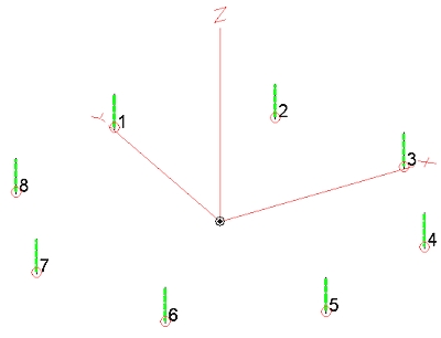
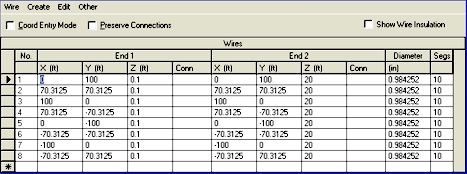
Basically there is a 20 foot active antenna element arranged every 45 degrees around the perimeter of a 200 foot diameter circle. The controller is located at the center of the array and receives signals from each antenna element via 8 identical coaxial cables. The EZNEC dimensions are in the following table.
Optimizing this
array required evaluating what effect array dimensions, element current, and
element phase had on the results I desired. My number one target was as high an
RDF as I could get while maintaining a reasonable front to back of at least 15
db. My second goal was to get as small an array as possible without
compromising RDF. My first attempts at varying amplitude and phasing were
successful in producing an antenna slightly better than the 4-element active
broadside array. Continuing with optimization produced better results as I
reduced the physical size of the array with the best RDF at 200 ft. diameter.
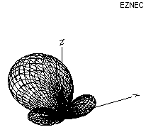
At this point in my optimization I reached a decision point where it became
apparent that a very clean looking pattern could be realized with some
degradation of the RDF. With RDF my primary goal the final pattern resulted in
some fairly high side lobes and a really good front to back ratio. While
optimizing this last step it became apparent that one could then easily clean
up the pattern by changing the element currents with the possibility of
electrically switching between modes. After looking at various combinations of
current distribution and phasing I was able to obtain the best RDF with all
elements being fed the same current level and a somewhat unique phase
distribution.
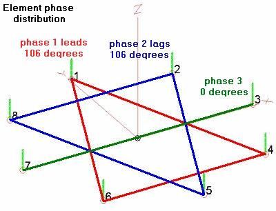
There are three basic phase channels used to process signals from the elements in this array. Three elements are connected to one phase channel, three elements with another phase channel and two fed with the last phase channel input. The three channels are then combined to a single output. As an incoming wave front passes the array it encounters 5 specific phases at specific element groups. The wave front encounters first one element then 2, then 2, then2, and lastly 1. This sets up a basic quasi-binomial current distribution in the array when all are mixed with equal gains.
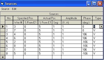
Eznec excitation sources are as follows in the table of values.
The resultant
patterns and performance figures for this array have greatly surpassed my
expectations. The following patterns and evaluations are presented by using a
fixed excitation for each element with Eznec. The gain figures listed have no
bearing on the actual array gain compared to any real radiator as each element
has been implemented with a high impedance buffer amplifier which results in a
considerable antenna mismatch loss. In reality this complete antenna array has
considerable loss from using its active elements that has to be made up with
post amplification. All relative gains and RDF are as accurate as can be
expected however the absolute values reflect what the antenna would produce if
actual power transfer were to take place.
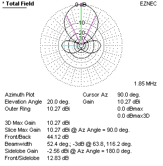
Calculating
the RDF of this array by subtracting the –3.18db of average gain from the
+10.27db of max gain in the desired direction results in RDF=13.45. An
outstanding RDF realized in only a 200-foot diameter circle. The Eznec plotted
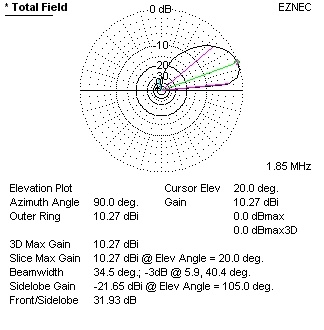
front to back ratio shows over 40db with only a 52-degree beamwidth! All this
RDF performance realized at an elevation angle of 20 degrees. As a comparison a
typical 1000-foot Beverage antenna produces an RDF of 12.3db at the same 20
degrees elevation.
Table 1 RX antenna Comparison Chart
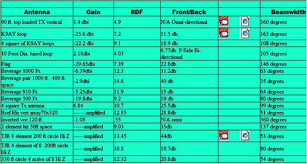
Click image for latest full page information in new window
For more comparisons see ON4UN Low Band Dxing book. The Elements, High Z amps, and the controller are described in the following chapters.
copyright K7TJR
Page 2
![]()
![]()
![]()
![]()