3 Element All Active High Impedance Receiving Array
![]()
![]() K7TJRcopyright
K7TJRcopyright
![]()
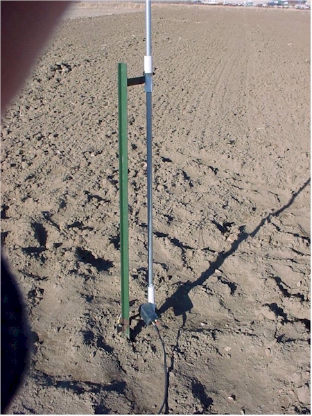
The elements used in this array are the same construction as used in other K7TJR arrays. They are insulated 20-foot sections of tubing arranged as a vertical element close to ground. A ground rod is needed in addition for connection to the high impedance amplifier.
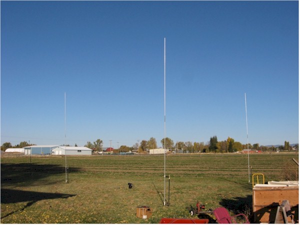
Actual operating 40 foot side array at K7TJR
The block diagram of the controller circuitry is as follows.
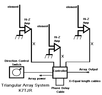
Each of the interconnecting cables of this array can be any length as long as they are equal length with 2 inches or so and they are from the same spool of cable. The phase delay cable is chosen depending on the side length of the array and the RDF/Front to back compromises. It is suggested that this value be chosen by using an antenna analysis program such as Eznec.
Down load Eznec file here
![]() For a 50 foot side Triangle array.
For a 50 foot side Triangle array.
The following charts show some suggested phasing values for different array side dimensions and desired performance. The first chart shows The RDF values available versus side dimension.
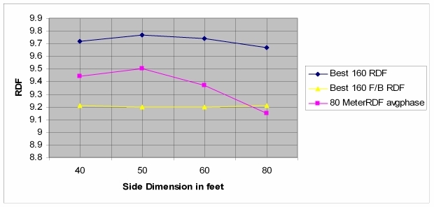
Best 160 F/B RDF above means the RDF available when the array phasing is set for best front to back ratio. The 80 meter values in the above plot are derived from a middle value of phasing. It is safe to say that the best RDF in this array for both 160 and 80 meters should occur around a 50 foot side dimension. The following chart shows the phasing values used to evaluate the best RDF and front to back ratios.
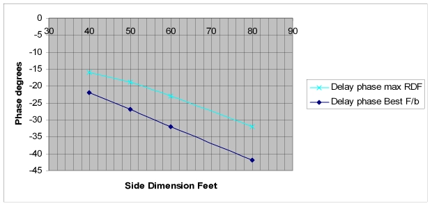
This chart shows the length of the delay line needed in degrees. The actual delay need for Eznec analysis will need to have -180 degrees added to the number. As you can see, the narrower the side dimension of the array, the smaller the delay cable and the smaller the difference between maximum RDF and front to back. This makes the smallest arrays critical to be constructed carefully and accurately. It also requires the controller to have accurate phase tracking and combining.
![]()
![]()
All web content copyright K7TJR