The 8 Element Controller![]()
![]()
![]()
![]()
The K7TJR
Array
![]() The controller
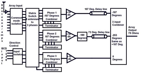
for this array is best described by breaking it down into sections. The job of
this controller is to combine all the signals from the 8 antennas and their
amplifiers producing the pattern as predicted by the antenna analysis software.
In order to do that the controller must select 3 certain antennas for a
107-degree delay (same as –253 degrees), 3 other antennas for a –107-degree
delay, and 2 more for a zero degree delay. It then combines them all together
for output to a receiver. It is important to understand that –253 degrees is
exactly equal to +107 degrees. Both these values are used interchangeably
throughout this description. By utilizing the value of –253 degrees it is a
little easier to visualize how this design can track phase over a varying
frequency range.
The controller
for this array is best described by breaking it down into sections. The job of
this controller is to combine all the signals from the 8 antennas and their
amplifiers producing the pattern as predicted by the antenna analysis software.
In order to do that the controller must select 3 certain antennas for a
107-degree delay (same as –253 degrees), 3 other antennas for a –107-degree
delay, and 2 more for a zero degree delay. It then combines them all together
for output to a receiver. It is important to understand that –253 degrees is
exactly equal to +107 degrees. Both these values are used interchangeably
throughout this description. By utilizing the value of –253 degrees it is a
little easier to visualize how this design can track phase over a varying
frequency range.
Early on in this antenna’s development it became obvious that common mode signals on the antenna inputs could destroy the pattern and RDF of this array. Being that the array has over 30db of front to back and utilizes a very low average 3D response it should be obvious that all stray signals must be attenuated to a high degree (well over 30db). With RDF calculated from average 3D response and a fixed forward gain it follows that for maximum RDF one must maintain as low as possible average 3D response. No stray pickup. Every signal path and every power supply path is filtered or supplied with common mode isolation.
Having the proper load on the
cables makes the phase delay of the signals be only affected by the cable length
and its velocity factor. Making all 8 connecting cables the same physical length
and materials takes their constant and equal phase delay out of the picture. The
only exceptions to the 75-Ohm signal paths are in the phase1, phase2, and 3
input combiners where the internal impedances are matched then stepped back up
to 75 Ohms.
The Direction control inputs use a transistor and a series of diodes to translate the TTL logic level to a somewhat more protected input. The addition of diodes to these inputs allows an over voltage of plus or minus 50 Volts to be applied without damage. Actual switching level is at +1.4 Volts sourcing 0.5 milliamps like TTL. This allows the input to simply be switched by grounding the input with a BCD switch or any TTL device.
Three antennas
are fed to the –107-degree combiner, three are fed to the +107-degree combiner
and two are fed to the zero degree combiner. An array of two input Magic Tee
combiners are used to implement a 4-channel combiner for both the –107 channel
and the +107 channel. A single two input combiner is used to combine the Zero
degree signals. The output impedance of the combiners is stepped back up to 75
ohms for application to the +10db amplifiers. The +10db amplifiers use heavy
feedback to provide a 75-Ohm input and output impedance. They also use a heavy
bias current to keep the third order inter-modulation distortion to a minimum.
Feedback resistance is adjusted to trim voltage gain for each channel. The
output transformer of the +107 degree (also same as –253 degrees) amplifier is
used to add a 180-degree phase lag for its channel. This does two things, one
it minimizes the amount of delay cable needed, and it makes both the –107
degree and the –253 degree delay cables similar in length (107 and 73 degrees).
This makes the controller phase delays match more closely the physical wave
delays for varying frequencies as the wave travels across the antenna array. In
effect this makes the array work over a wider frequency band than if just fixed
delay lines were used. Because the zero degree signal-channel has fewer
transformers in its path a little phase delay compensation must be added. The
10db amplifier in the zero-degree channel also has a phase trim adjustment.
After processing through their required delay cables all three signals are fed to a unique 3-input combiner. This combiner is fed to a 6db attenuator circuit, which evens out any impedance mismatches that may occur as a result of unknown impedances being connected at the receiver output.
Page 4
copyright K7TJR
![]()
![]()
![]()
![]()